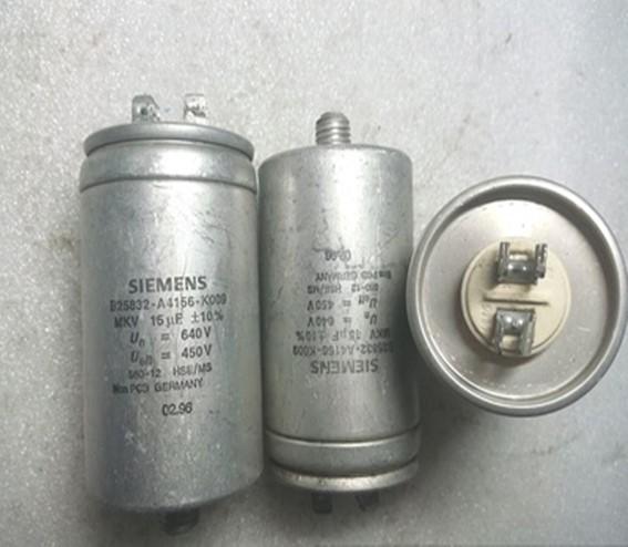
Two conductors close to each other, sandwiched by a layer of non-conductive insulating medium, which constitutes a capacitor. When a voltage is applied between the two plates of the capacitor, the capacitor will store charge. The capacitance of the capacitor is numerically equal to the ratio of the amount of charge on one conductive plate to the voltage between the two plates. The basic unit of the capacitance of a capacitor is farad (F). In the circuit diagram, the letter C is usually used to indicate the capacitive element.
Capacitors play an important role in circuits such as tuning, bypassing, coupling, and filtering. It is used in the tuning circuit of the transistor radio, as well as the coupling circuit and bypass circuit of the color TV.
With the rapid development of electronic information technology, digital electronic products are being updated faster and faster. The production and sales of consumer electronic products, mainly flat-panel TVs (LCDs and PDPs), notebook computers, digital cameras, and other products, continue to grow, driving The capacitor industry is growing.
7SJ82, 7SJ85, 7SR191, B43458-A5478-M3, 385V4600UF, B43586-S3468-Q1, B43586-S3468-Q2, B43586-S3468-Q3, B43456-A9478-M, B43252-A5567-M, 3RT16471AV01, B43586-S9578-Q1, B43586-S9578-Q2, B43586-S9578-Q3, B32674-D6225-K, B43231-A9477-M, B32678-G6256-K, B43564-S9578-M1, B43564-S9578-M2, B43564-S9578-M3, B43508-C9227-M

Конденсатор банкынын коргоосу коргоо түзүлүшүнүн интеграцияланган функциясы катары
Capacitors and capacitor banks are used for various applications. Examples are: Reactive-power compensation for voltage stabilization, fast voltage- and reactive-power control or filter circuits for the elimination of certain frequencies. Capacitor banks for transmission systems are complex systems customized for the special application. The design depends much on the used switching technology (for example, mechanically or via thyristor). In detail hardly one capacitor bank resembles another. However, a capacitor bank consists always of the same components (C, R, L, and switches). A capacitor bank often consists of several subcomponents which are connected to the capacitor-bank busbar via the circuit breakers. The modularity of hardware and protection functionality allows to tailor the protection device exactly to the needs of the capacitor bank or the sub component of the capacitor bank and to realize the complete protection of the whole capacitor bank or the capacitor- bank sub component with only one SIPROTEC 7SJ8 device. Capacitor banks require the use of extensive protection functionality. The protection consists of standard protection functions and specific capacitor protection functions.
1. Overcurrent and feeder protection- SIPROTEC 7SJ82
The SIPROTEC 7SJ82 overcurrent protection has specifically been designed for a cost-effective and compact protection of feeders, lines and capacitor banks in medium-voltage and high-voltage systems. With its flexibility and the powerful DIGSI 5 engineering tool, the SIPROTEC 7SJ82 device offers future-oriented system solutions with high investment security and low operating costs.
1) Өзгөчөлүктөрү
Негизги милдети:
Feeder and overcurrent protection for all voltage levels
Кириштер жана чыгуулар:
4 current transformers,
4 voltage transformers (optional),
11 or 23 binary inputs,
9 or 16 binary outputs,
or
8 current transformers,
7 binary inputs,
7 binary outputs
Hardware flexibility:
Different hardware quantity structures for binary inputs and outputs are available in the 1/3 base module. Adding 1/6 expansion modules is not possible; available with large or small display.
Турак туурасы:
1/3 × 19 inches
2) Functions
DIGSI 5 бардык функцияларды талапка ылайык конфигурациялоого жана бириктирүүгө мүмкүндүк берет.
Directional and non-directional overcurrent protection with additional functions
Optimized tripping times due to directional comparison and protection data communication
Detection of ground faults of any type in compensated or isolated electrical power systems using the following functions: 3I0>, V0>, transient ground fault, cos φ, sin φ, harmonic, dir. Detection of intermittent ground faults and admittance
Ground fault detection using the pulse detection method
Arc protection
Ашкере чыңалуудан жана чыңалуудан коргоо
Frequency protection and frequency change protection for load shedding applications
Automatic frequency relief for underfrequency load shedding, taking changed infeed conditions due to decentralized power generation into consideration
Power protection, configurable as active or reactive power protection
Protection functions for capacitor banks, such as overcurrent, overload, current unbalance, peak overvoltage, or differential protection
Directional reactive power undervoltage protection (QU protection)
Control, synchrocheck and switchgear interlocking protection, circuit-breaker failure protection
Circuit-Breaker Failure Protection
Circuit breaker reignition monitoring
Graphical logic editor to create powerful automation functions in the device
Detection of current and voltage signals up to the 50th harmonic with high accuracy for selected protection functions (such as peak overvoltage protection for capacitors) and operational measured values
Single-line representation in small or large display
Integrated electrical Ethernet RJ45 for DIGSI 5 and IEC 61850 (reporting and GOOSE)
2 optional, pluggable communication modules, usable for different and redundant protocols (IEC 61850-8-1, IEC 60870-5-103, IEC 60870-5-104, Modbus TCP, DNP3 serial and TCP, PROFINET IO)
Serial protection data communication via optical fibers, two-wire connections and communication networks (IEEE C37.94, and others), including automatic switchover between ring and chain topology
PRP жана HSR ашыкча протоколдор аркылуу ишенимдүү маалыматтарды берүү
Extensive cyber security functionality, such as role-based access control (RBAC), protocolling security-related events or signed firmware
Simple, quick and secure access to device data via a standard Web browser – without additional software
Whitepaper Phasor Measurement Unit (PMU) for synchrophasor measured values and IEEE C37.118 protocol
Time synchronization using IEEE 1588
Control of Power Transformers
Powerful fault recording (buffer for a max. record time of 80 sec. at 8 kHz or 320 sec. at 2 kHz)
Жөнөкөй сыноолор жана ишке киргизүү үчүн көмөкчү функциялар
3) Тиркемелер
Detection and selective 3-pole tripping of short circuits in electrical equipment of star networks, lines with infeed at one or two ends, parallel lines and open-circuited or closed ring systems of all voltage levels
Detection of ground faults in isolated or arc-suppression-coil-ground power systems in star, ring, or meshed arrangement
Backup protection for differential protection devices of all kind for lines, transformers, generators, motors, and busbars
Protection and monitoring of simple capacitor banks
Phasor Measurement Unit (PMU)
Reverse-power protection
Load shedding applications
Automatic switchover
Regulation or control of power transformers (two-winding transformers)
4) Benefits
Compact and low-cost overcurrent protection
Safety due to powerful protection functions
Data security and transparency over the entire lifecycle of the plant, saving time and money
Колдонуучуга ыңгайлуу дизайндын аркасында түзмөктөрдү жана программалык камсыздоону максаттуу жана жеңил иштетүү
Инженердик процесстин ишенимдүүлүгүн жана сапатын жогорулатуу
Cyber security to NERC CIP and BDEW Whitepaper requirements (for example, protocolling security-related events and alarms)
Highest availability even under extreme environmental conditions by “conformal coating“ of electronic boards
Powerful communication components warrant safe and effective solutions
Full compatibility between IEC 61850 Editions 1 and 2
High investment security and low operating costs due to future-oriented system solutions

2. Overcurrent and feeder protection- SIPROTEC 7SJ85
The SIPROTEC 7SJ85 overcurrent protection has been designed specifically for the protection of feeders, lines and capacitor banks. With its modular structure, flexibility and the powerful DIGSI 5 engineering tool, the SIPROTEC 7SJ85 device offers future-oriented system solutions with high investment security and low operating costs.
1) Өзгөчөлүктөрү
Негизги милдети:
Feeder and overcurrent protection for all voltage levels
Кириштер жана чыгуулар:
5 predefined standard variants with
4 current transformers,
4 voltage transformers,
11 to 59 binary inputs,
9 to 33 binary outputs
Hardware flexibility:
Flexibly adjustable and expandable I/O quantity structure within the scope of the modular SIPROTEC 5 system; 1/6 expansion modules can be added, available with large or small display, or without display
Турак туурасы:
1/3 × 19 inches to 2/1 × 19 inches
2) Functions
DIGSI 5 бардык функцияларды талапка ылайык конфигурациялоого жана бириктирүүгө мүмкүндүк берет.
Directional and non-directional overcurrent protection with additional functions
Protection of up to 9 feeders with up to 40 analog inputs
Optimized tripping times due to directional comparison and protection data communication
Detection of ground faults of any type in compensated or isolated electrical power systems using the following functions: 3I0>, V0>, transient ground fault, cos φ, sin φ, harmonic, dir. Detection of intermittent ground faults and admittance
Ground fault detection using the pulse detection method
Fault locator plus for accurate fault location with inhomogenous line sections and targeted automatic overhead-line section reclosing (AREC)
Arc protection
Overvoltage and undervoltage protection.
Power protection, configurable as active or reactive power protection.
Frequency protection and frequency change protection for load shedding applications.
Automatic frequency relief for underfrequency load shedding, taking changed infeed conditions due to decentralized power generation into consideration.
Protection functions for capacitor banks, such as overcurrent, overload, current unbalance, peak overvoltage, or differential protection.
Directional reactive power undervoltage protection (QU protection).
Detection of current and voltage signals up to the 50th harmonic with high accuracy for selected protection functions (such as peak overvoltage protection for capacitors) and operational measured values.
Point-on-wave switching.
Control, synchrocheck and switchgear interlocking protection.
Circuit-Breaker Failure Protection.
Circuit breaker reignition monitoring.
Graphical logic editor to create powerful automation functions in the device.
Single-line representation in small or large display.
Fixed integrated electrical Ethernet RJ45 for DIGSI 5 and IEC 61850 (reporting and GOOSE).
Up to 4 pluggable communication modules, usable for different and redundant protocols (IEC 61850-8-1, IEC 61850-9-2 Client, IEC 61850-9-2 Merging Unit, IEC 60870-5-103, IEC 60870-5-104, Modbus TCP, DNP3 serial and TCP, PROFINET IO)
Serial protection data communication via optical fibers, two-wire connections and communication networks (IEEE C37.94, and others), including automatic switchover between ring and chain topology.
PRP жана HSR ашыкча протоколдор аркылуу ишенимдүү маалыматтарды берүү
Extensive cyber security functionality, such as role-based access control (RBAC), protocolling security-related events or signed firmware.
Simple, quick and secure access to device data via a standard Web browser – without additional software.
Phasor Measurement Unit (PMU) for synchrophasor measured values and IEEE C37.118 protocol.
Time synchronization using IEEE 1588.
Control of Power Transformers.
Powerful fault recording (buffer for a max. record time of 80 sec. at 8 kHz or 320 sec. at 2 kHz).
Auxiliary functions for simple tests and commissioning.

3) Benefits
Safety due to powerful protection functions
Data security and transparency over the entire lifecycle of the plant, saving time and money
Колдонуучуга ыңгайлуу дизайндын аркасында түзмөктөрдү жана программалык камсыздоону максаттуу жана жеңил иштетүү
Инженердик процесстин ишенимдүүлүгүн жана сапатын жогорулатуу
Cyber security in accordance with NERC CIP and BDEW Whitepaper requirements
Highest availability even under extreme environmental conditions by “conformal coating“ of electronic boards
Powerful communication components warrant safe and effective solutions
Full compatibility between IEC 61850 Editions 1 and 2
High investment security and low operating costs due to future-oriented system solutions
Capacitor bank protection- Reyrolle 7SR191
The 7SR191 Capa is a numerical protection relay with a highly comprehensive functional software package.
1) Өзгөчөлүктөрү
The market for power capacitors is continually growing due to the expanding power network driven by increased customer demand. Power capacitors improve the performance, quality and efficiency of the system and minimize power loss. The Reyrolle 7SR191 Capa protection relay is designed with all of the necessary functionality for use on shunt connected distribution capacitor banks arranged in all of the common connection configurations:
Single star
Double star
Delta
H configuration
The Reyrolle 7SR191 Capa is a numerical protection device with a highly comprehensive functional software package which includes a range of integral application functions aimed at reducing installation, commissioning, wiring and engineering time.
User selectable hardware configuration to suit different bank arrangements
- 3 pole overcurrent + 1 pole unbalance
- 1 pole overcurrent + 3 pole unbalance
Optional voltage inputs
Re-energisation blocking to prevent CB closing until the bank has self discharged
Overvoltage protection by integration analysis of current
Suitable for use with both internally/externally fused and fuseless capacitors
User programmable characteristics for all inverse voltage, current and thermal curves
Unbalance protection with natural spill compensation
2) Functions
Коргоо функциялары
Fascia programmable
CB control via fascia, binary inputs and communication SCADA system
User definable logic both via Quicklogic equations and a graphical design tool
Multiple setting groups
Өлчөнгөн баалуулуктар
Fault records
Disturbance waveform records
Иш-чаранын жазуулары
6 User alarms for LCD text indications
Trip circuit supervision
Close circuit supervision
Virtual input/output
CB operation counts
Demand metering
Harmonic analysis and THD
Undercurrent/Loss of Supply (37)
Phase unbalance (46M)
Negative phase sequence overcurrent (46NPS)
Thermal overload (49)
Instantaneous overcurrent (50)
Instantaneous earth fault (50N)
Circuit breaker fail (50BF)
Time delayed overcurrent (51)
Time delayed derived earth fault (51N)
Overvoltage by current integration (59C)
Capacitor unbalance current (60C)
High impedance REF (87REF)
Under/overvoltage (27/59)
Negative phase sequence voltage (47)
Neutral voltage displacement (59N)
Directional instantaneous overcurrent (67/50)
Directional instantaneous rarth fault (67/50N)
Directional time delayed overcurrent (67/51)
Directional time delayed earth fault (67/51N)
Under/over frequency (81)

In a DC circuit, the capacitor is equivalent to an open circuit. A capacitor is an element capable of storing charge, and is also one of the most commonly used electronic components.
This must start from the structure of the capacitor. The simplest capacitor is composed of polar plates at both ends and an insulating dielectric (including air) in the middle. After being energized, the plates are charged, forming a voltage (potential difference), but due to the insulating material in the middle, the entire capacitor is not conductive. However, this situation is under the premise that the critical voltage (breakdown voltage) of the capacitor is not exceeded. We know that any substance is relatively insulated. When the voltage across the substance increases to a certain level, the substance can be conductive. We call this voltage the breakdown voltage. Capacitors are no exception. After a capacitor is broken down, it is no longer an insulator. However, in the middle school, such voltages are not seen in the circuit, so they work below the breakdown voltage and can be regarded as insulators.
However, in AC circuits, the direction of the current changes as a function of time. The process of charging and discharging the capacitor has time. At this time, a changing electric field is formed between the plates, and this electric field is also a function of changing with time. In fact, current flows between capacitors in the form of an electric field.
The role of capacitors:
● Coupling: The capacitor used in the coupling circuit is called the coupling capacitor. This type of capacitive circuit is widely used in the resistance-capacitance coupling amplifier and other capacitive coupling circuits to play the role of blocking DC and AC.
● Filter: The capacitor used in the filter circuit is called the filter capacitor. This capacitor circuit is used in the power supply filter and various filter circuits. The filter capacitor removes the signal in a certain frequency band from the total signal.
● Decoupling: The capacitor used in the decoupling circuit is called the decoupling capacitor. This capacitor circuit is used in the DC voltage supply circuit of the multi-stage amplifier. The decoupling capacitor eliminates the harmful low-frequency cross-connection between each stage of the amplifier.
● High frequency vibration elimination: the capacitor used in the high frequency vibration elimination circuit is called the high frequency vibration elimination capacitor. In the audio negative feedback amplifier, in order to eliminate the high frequency self-excitation that may occur, this capacitor circuit is used to eliminate High frequency howling that may occur in the amplifier.
● Resonance: The capacitor used in the LC resonant circuit is called the resonant capacitor. This capacitor circuit is required in both LC parallel and series resonant circuits.
● Bypass: The capacitor used in the bypass circuit is called the bypass capacitor. If you need to remove a certain frequency band signal from the signal in the circuit, you can use the bypass capacitor circuit. According to the frequency of the removed signal, there is a full frequency domain (All AC signals) Bypass capacitor circuit and high frequency bypass capacitor circuit.
● Neutralization: The capacitor used in the neutralization circuit is called neutralization capacitor. This kind of neutralizing capacitor circuit is used in high-frequency and intermediate-frequency amplifiers of radios and high-frequency amplifiers of televisions to eliminate self-excitation.
● Timing: The capacitor used in the timing circuit is called the timing capacitor. Timing capacitor circuits are used in circuits that require time control through capacitor charging and discharging, and the capacitor plays a role in controlling the size of the time constant.
● Integration: The capacitor used in the integration circuit is called the integration capacitor. In the synchronous separation circuit of potential field scanning, this integration capacitor circuit can be used to extract the field synchronization signal from the field composite synchronization signal.
● Differential: The capacitor used in the differential circuit is called the differential capacitor. In order to get the apex trigger signal in the trigger circuit, this kind of differential capacitor circuit is used to get the apex pulse trigger signal from various types (mainly rectangular pulse) signals.

● Compensation: The capacitor used in the compensation circuit is called the compensation capacitor. In the bass compensation circuit of the deck, this low-frequency compensation capacitor circuit is used to enhance the low-frequency signal in the playback signal. In addition, there is a high-frequency compensation capacitor Circuit.
● Booststroke: The capacitor used in the bootstrap circuit is called the bootstrap capacitor. The commonly used OTL power amplifier output stage circuit uses this bootstrap capacitor circuit to slightly increase the positive half-cycle amplitude of the signal through positive feedback.
● Frequency division: The capacitor in the frequency division circuit is called the frequency division capacitor. In the speaker frequency division circuit of the speaker, the frequency division capacitor circuit is used to make the high frequency speaker work in the high frequency band, and the intermediate frequency speaker works in the middle frequency band, low frequency The speaker works in the low frequency band.
● Load capacitance: refers to the effective external capacitance that determines the load resonance frequency together with the quartz crystal resonator. Commonly used standard values for load capacitance are 16pF, 20pF, 30pF, 50pF and 100pF. The load capacitance can be adjusted appropriately according to the specific situation, and the operating frequency of the resonator can generally be adjusted to the nominal value through adjustment.
